The Tronsys winch will come with a “How to use” guide and a connector cable for your UAV.
The video above provides a short demo on how to connect and operate your winch.
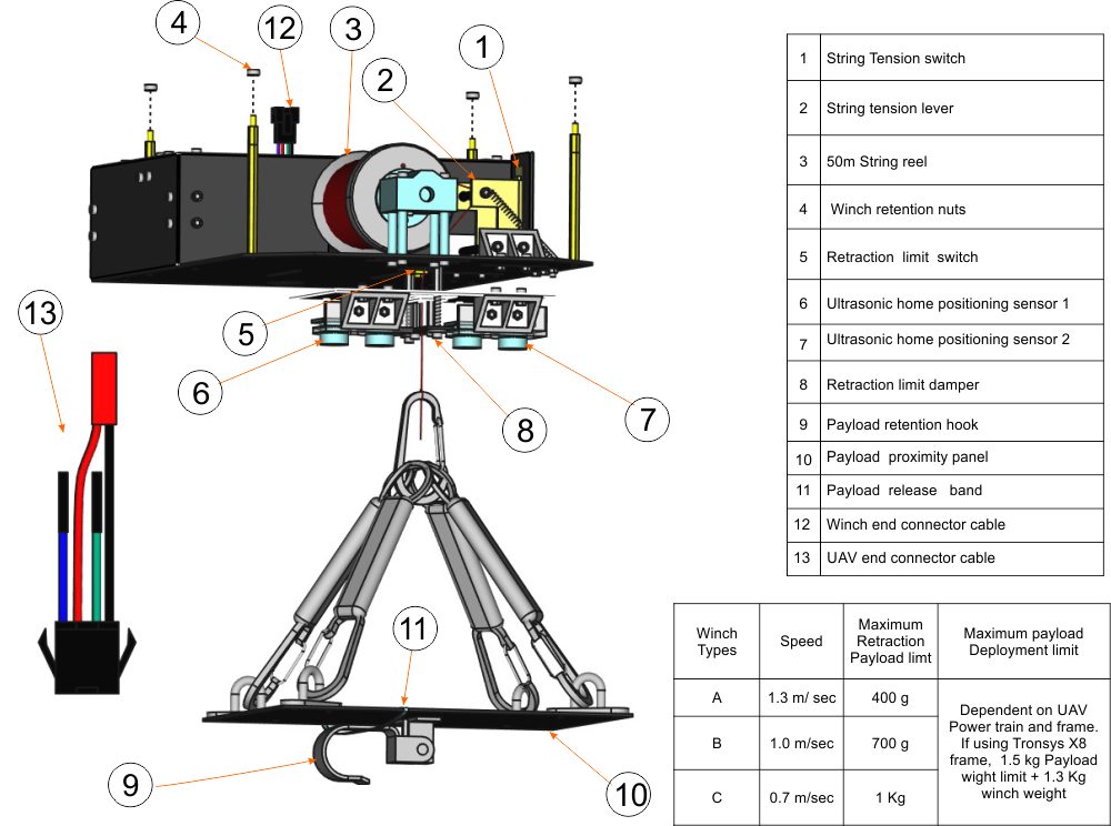
Fig.1 shows all the main features of your winch. Each feature will be referenced numerically throughout the rest of this guide.
(section A) What follows is a step-by-step guide on how to connect and use your winch.
Ensure there are four location holes on your frame, 184 mm by 184 mm spacing. This is to secure the winch to your frame using the four M3 bolt features and locking nuts (4).
Manoeuvre the four location bolts of the winch into the above mention location holes with the chamfered end of the winch facing the forward end of the UAV. Then secure with the locking nuts(4).
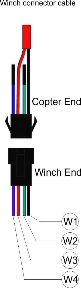
Locate the UAV end of the winch connector cable (13). Plug the green wire into a RC channel of your UAV. Plug the blue wire into the signal of a servo output pin of your flight controller. Plug the JST power plug into a power source (6S).
Warning: Before plugging the winch part of the connector cable to the UAV part of the cable, ensure the payload proximity panel(10) is clipped in position beneath the winch as shown in fig.1.
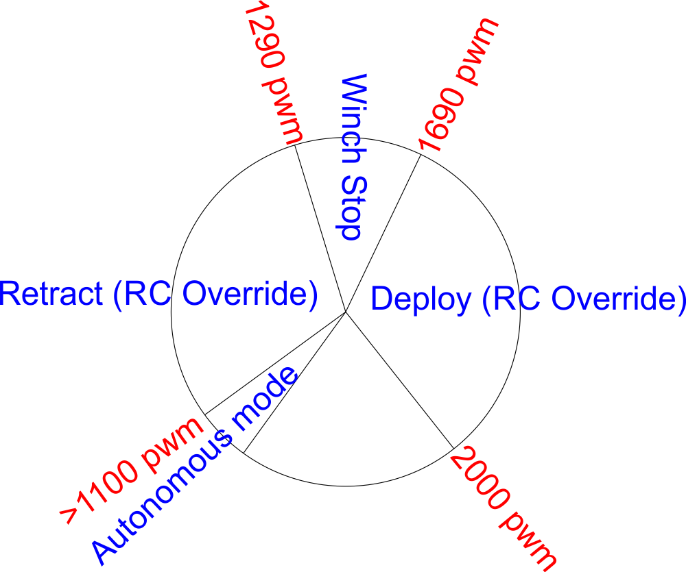
Fig.2 Tronsys winch RC control
(Section B) RC Settings
For best performance, set a RC rotary switch(Knob) on your transmitter for the channel to control the winch. For this illustration we chose transmitter channel 11.
Connect the green wire(13) to a channel on your receiver or a servo pin on your flight controller set for RC pass thru on the transmitter rotary switch (knob).
Rotating the knob to the counter clockwise limit allows the winch to receive autonomous commands from the autopilot through the blue wire. (See fig.2)
Slightly rotating clockwise from the limit overrides autonomous commands and causes the winch to retract to home position. (Home position is just below the Ultrasonic sensors (6 & 7)).
Further clockwise rotation causes the winch to stop at mid range pwm values.
Further clockwise rotation to the limit causes the winch to deploy its payload. On touch down, the hook is elastically retracted by a band(10) causing the payload to be released. The releasing of the payload causes the string to relax, thus activating the string tension switch(1). This triggers the retraction of the winch to its home position without any further input from the operator.
The winch is reset by counter clockwise rotation of the RC knob passed the mid range pwm values.
Further clockwise rotation will redeploy the winch.
This cycle is repeated for RC manual overrides and control of the winch by the operator. 1
(Section C) Autonomous settings.
Autonomous mode allows control of the winch from the flight controller or ground station instead of the RC transmitter. For this illustration we will be using Mission Planner as the ground station.
What follows is a step by step guide for setting autonomous commands to the winch
Ensure your UAV is all powered up and winch connected as described in section A.
Connect your UAV to your ground station (e.g. Mission Planner).
manually support your UAV off the ground to allow at least 1 m from the ground to the winch end-effector as illustrated in the video.
Although you can use any output channel of your choice, for this illustration we will be connecting the blue wire to output channel 11 on the flight controller.
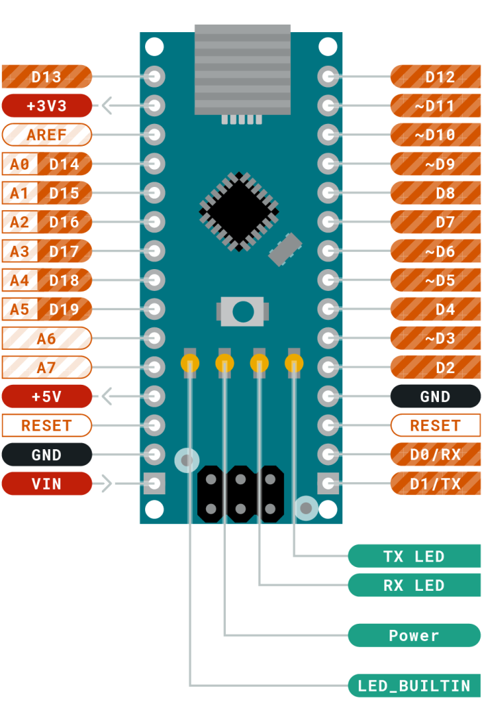
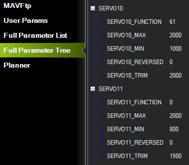
For sample parameter settings for output channel 11 see fig.3 (SERVO_11). When you perform an auto mission you can ask for a output channel to be set to a value as part of that mission. As this example has chosen output channel 11, we should set the SERVO11_FUNCTION for that channel to Disabled (0), so that the value doesn’t get changed by another output function immediately after the mission sets the value.
For this example, we plugged the green wire into flight controller output channel 10 for RC manual override of autonomous winch control.
For sample settings for output channel 10, see fig.3 (SERV0_10). For example, if SERVO10_FUNCTION is 61 (meaning RCPassThru), then channel 10 output will always be equal to RC channel 11 input. (For more details click here – Autopilot Output Functions )
Fig.3 Flight controller output channel settings
Autonomous winch commands
Enable autonomous mode by rotating transmitter switch to it counter clockwise limit (<1100 PWM).
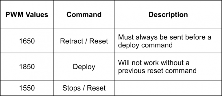
Table 1. Winch commands
Testing Autonomous Commands
In your ground station software (i.e. Mission Planner), navigate to the flight controllers output channel menu where to can send out pwm values.
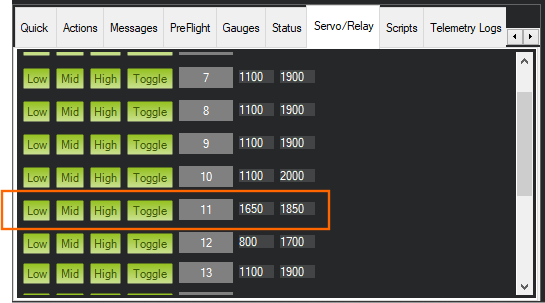
In mission planner, pwm values can be tested as shown in fig.4. To test, type in 1650 for low and 1850 for high for the output channel 11 as shown.
To start click the low button to reset the winch.
Now you can deploy the winch by clicking the high button.
To restart the cycle, click the reset low button again, then click the high button to deploy once more.
Fig.4 Winch servo test
Autonomous Winch Testing
Sample Mission Script ( For more details on planning missions click here )
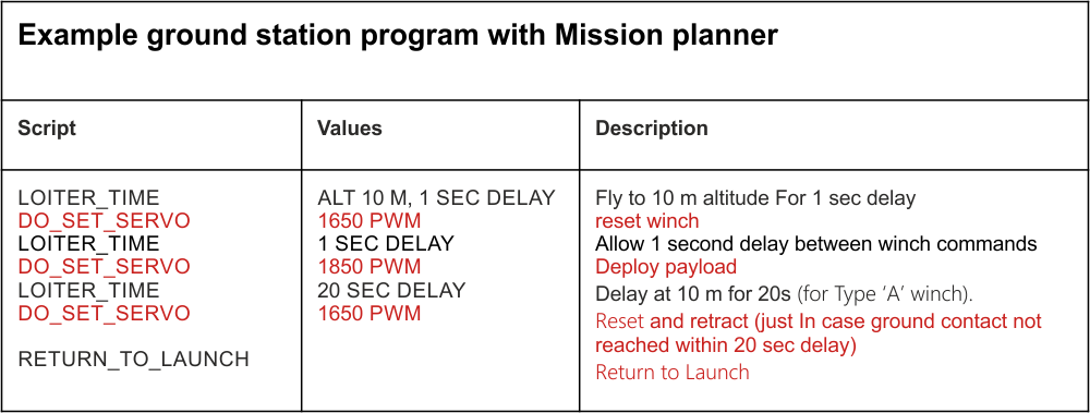
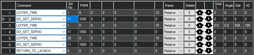
Fig.5 winch sample script with mission planner
Fig.6 Mission example using output servo channel 11
Payload Warnings
There are two types of winches on offer.
Type A
Type B
Type C
TYPE A
This winch is used where deployment speed is essential without any requirement for payload retrieval/retraction. Deployment speeds of 0.7m/sec are achievable making this which the fastest option available. However, this advantage is offset by low retraction limits. If payload exceeds 400g and payload fails to release on touch down, it is advised to manual override to loiter flight mode then to manual deploy again with RC controls until payload is released. loads under 400g can be allowed to retract back to UAV upon failed release.
For a sample time deploying autonomously from a height of 10 m, you will need to set a “Loiter” time of 15 sec to drop off the payload and retract empty to UAV.
TYPE B
This winch is the standard. It has a speed of 1 m /sec. This means that if you are deploying from a height of 10 m, you will need to set a “Loiter” time of 20 sec to drop of the payload and retract to home.
If by any chance you are retracting a payload to the UAV, you are only limited to retract a maximum of 700 g. Any excess of this may cause the winch to stall in retract mode thereby forcing you to lower the winch or copter to drop off payload manually.
TYPE C
This is a slightly stronger winch at the cost of slower deployment speed. Deployment speed is 1.5 m/second. This required a loiter time of 30 seconds to deploy from 10 m and to retract to UAV empty. However retraction limits of 1 kg is achievable making this winch the strongest option available at the cost of low speed .
TYPE A , B & TYPE C MAXIMUM DEPLOYMENT LOAD
Maximum deployment payloads is dependant on UAV powertrain and frame.
If using the Tronsys X8 power train and frame, a total of 3kg is maximum allowable load. This includes the weight of the winch at 1.3 kg. As a result, the maximum allowable load that can be deployed to earth is 1.7 Kg when using the Tronsys X8 UAV power train. The heavier the payload up to the limit of 1.7 Kg, the shorter the duration of flight due to battery constraints.